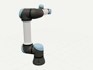
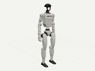
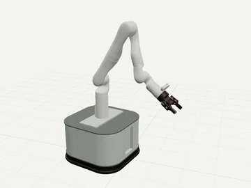
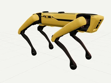
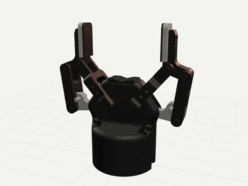
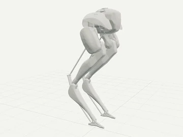
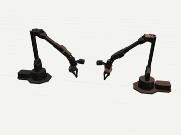
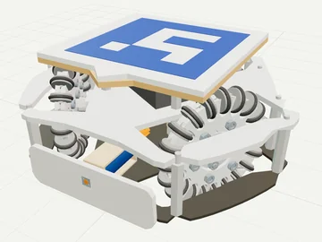
A picture guide for people new to robot hardware. Each diagram is our own drawing; the labels link to the parts, and the text links to the Design Book, where the numbers and their sources live.
Kinds of robots
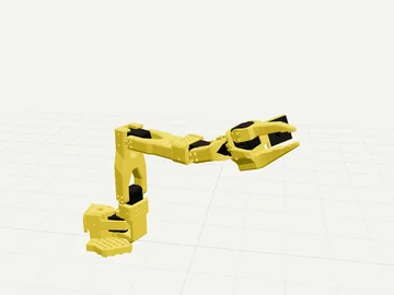
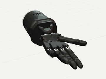
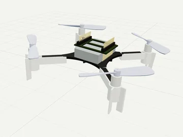
Each card shows an animated drawing of the parts and, where one exists, a 3D clip of a real open robot model. They pause when your system asks for reduced motion, or when you press Pause animations at the top of the page. The name opens the robots table for that kind.
A small arm is a chain of joints. Each joint has a servo; printed links join them; a bus carries commands from the computer. The SO-101 worked example sizes one.
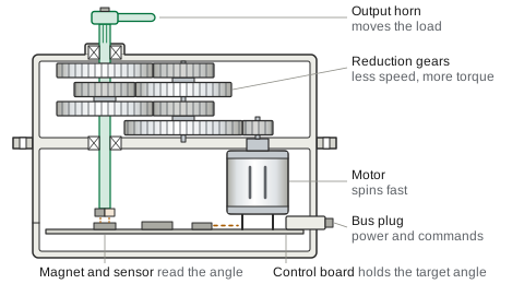
Inside one robot joint
Drawing: Suqoona Robotics. Schematic, not to scale.
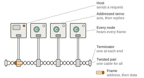
The computer sends targets; a bus adapter turns USB into the servo bus; every servo on the bus hears every frame and answers when asked. See TTL serial bus and Control loops.
How power flows
Drawing: Suqoona Robotics. Schematic, not to scale.
The battery feeds the motors through drivers and the logic through a converter; the BMS and the emergency stop sit in front of both. See Electrical and power and Safety.
How each part works
Animated diagrams. They pause when your system asks for reduced motion, or when you press Pause animations at the top of the page.
Actuation
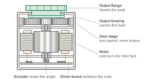
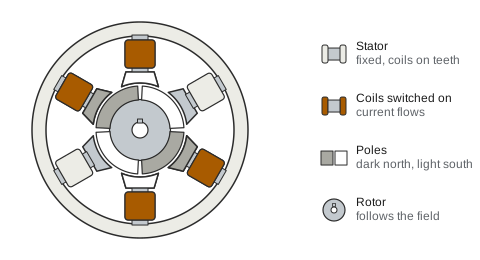
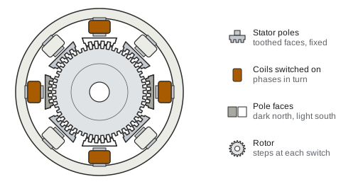
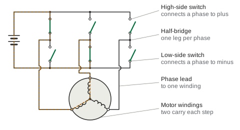
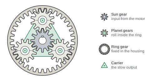
Servos: Servo cut-away: the motor turns a train of reduction gears, each stage slower than the one before; the last gear turns the output shaft and horn; a magnet on the shaft and a sensor on the control board read the angle, and the board drives the motor until the horn is at the target angleRobot actuators: Joint actuator cut along its axis: the motor's stator coils turn the rotor and its magnets fast; the sun gear on the rotor shaft drives planet gears that roll inside a fixed ring gear; the planet carrier turns five times slower and drives the output flange, which runs on the output bearing; a magnet on the end of the rotor shaft and a sensor chip on the driver board read the rotor angle, and the board switches the current in the coilsMotors: Brushless motor seen along its axis: six stator teeth carry coils of three phases; the drive switches current into two phases at a time, which makes one pair of opposite teeth north and another south; each switch moves this field a step round, and the rotor's four magnets, north and south in turn, follow it, so the rotor turnsMotors: Hybrid stepper motor seen along its axis: eight toothed stator poles round a rotor with fifty teeth; the drive switches the two phases in the order A, B, A reversed, B reversed; each switch makes a different pair of poles pull the rotor teeth into line, and the rotor turns one small step, a quarter of a tooth, each timeMotor drivers: Three-phase motor driver: six switches in three half-bridges feed the three windings of a motor; in six steps that repeat in order, one high-side and one low-side switch of two different legs close, and current flows from plus through one winding and out through another; the two switches of one leg are never on together
Transmission
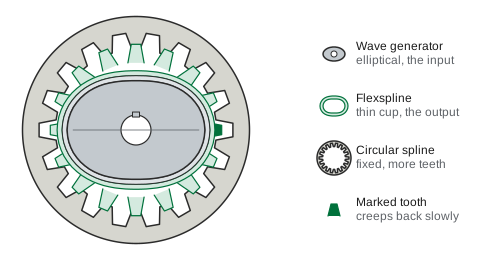
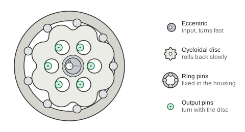
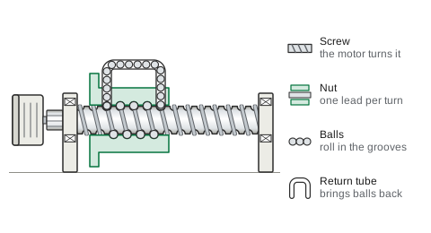
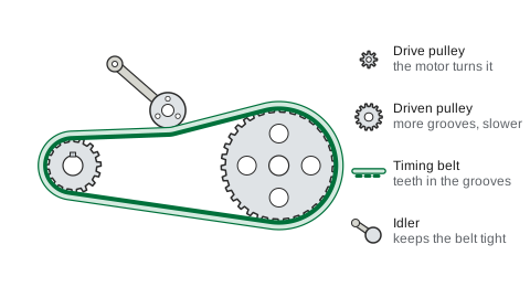
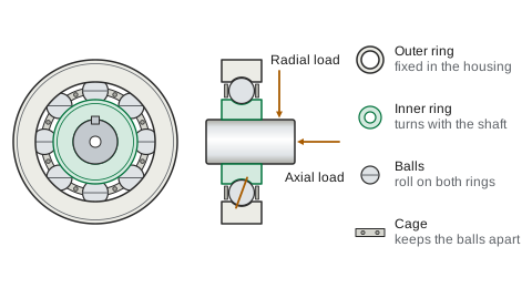
Gearboxes: Planetary gearbox: the sun gear in the middle is the input; three planet gears on a carrier mesh with the sun and roll inside a fixed ring gear; the carrier that holds the planets is the output and turns four times slower than the sun, in the same directionGearboxes: Strain wave gear: the elliptical wave generator is the input and turns fast; it bends the thin flexspline so that its teeth mesh with the fixed circular spline at two zones on the long axis; the flexspline has two teeth fewer, so for each turn of the wave generator it turns back by two teeth; the flexspline is the outputGearboxes: Cycloidal drive: the input shaft turns an eccentric fast; the eccentric moves a lobed disc round inside a ring of fixed pins; the disc has one lobe fewer than there are pins, so for each turn of the input it rolls back by one lobe; pins of the output flange sit in holes in the disc and turn with it, slowly and the other wayScrews and linear: Ball screw: the motor turns the screw; the nut cannot turn, so it moves along the screw by one lead for each turn; balls roll between the grooves of the screw and the nut, and a tube in the nut brings them back from one end of the track to the other; when the motor turns back, the nut comes backBelts: Timing belt drive: the motor turns the small drive pulley; the teeth of the belt sit in the pulley grooves, so the belt cannot slip; the large driven pulley has twice the grooves and turns at half the speed; an idler on the slack side keeps the belt tightBearings: Deep groove ball bearing: the outer ring is fixed in the housing and the inner ring turns with the shaft; the balls roll between the two rings and spin as they go, and the cage that keeps them apart goes round at a bit under half the speed of the shaft; the section shows how the rings carry a radial load and an axial load through the balls
Sensing
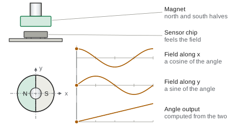
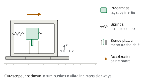
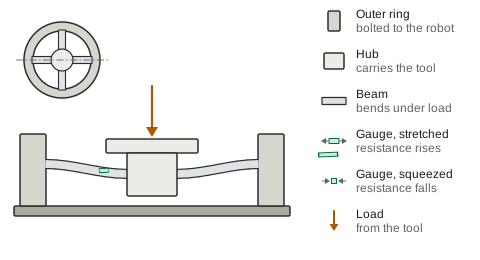
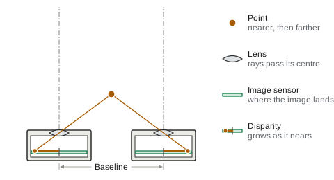
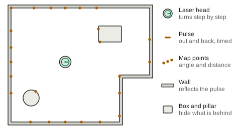
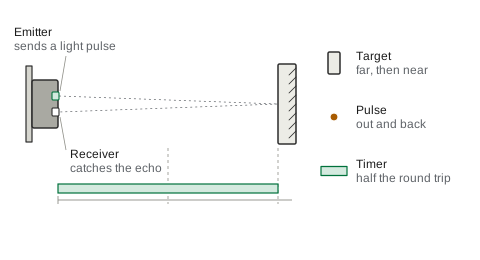
Encoders and magnetic sensors: Magnetic encoder: a magnet with a north half and a south half turns on the shaft end above an angle-sensor chip. Under the magnet the field lies across the chip and points from the north half to the south half, so it turns with the shaft. The chip measures the field along x, which traces a cosine, and along y, which traces a sine; the angle output is computed from the two and rises steadily through one turnIMUs: IMU accelerometer: the board speeds up to the right, runs steadily, slows down and stops, then comes back. Inside the chip, drawn cut open and much enlarged, a proof mass hangs on springs: it lags to the left while the board speeds up, sits in the middle at steady speed, and moves right while the board slows down, because its inertia resists the change. The shift changes the gaps to fixed plates, and the chip measures that. The x, y and z axes ride with the chip, one such mass for each axis. Gyroscope, not drawn: a mass kept vibrating, which a turn pushes sidewaysForce and torque: Six-axis force-torque sensor, section through two of its beams, bending much exaggerated: an inner hub that carries the tool is joined to an outer ring bolted to the robot by stiff beams. A push on the tool moves the hub down and bends each beam into an S shape. On the top face of a beam, the strain gauge near the ring is stretched and its resistance rises, while the gauge near the hub is squeezed and its resistance falls. Gauges on all the beams together give the three forces and three torquesCameras: Stereo depth camera, seen from above: two cameras a baseline apart, each a lens with an image sensor behind it. A point sends a ray straight through the centre of each lens; where the rays land, the point's two images sit off the middle of the sensors. By similar triangles the shift between the two images (the disparity) is the baseline times the lens-to-sensor distance divided by the depth, so as the point comes three times nearer the shift grows three times; the camera turns the shift into depthLiDAR: Scanning lidar, top view of a room: the laser head turns step by step; at each step it sends a light pulse that reflects from the first surface and comes back. The time out and back gives the distance, so far walls answer later, and each answer adds a point to the map at that angle and distance. The box and the pillar hide the wall behind them. Light is slowed down here to be seenDistance (ToF): Time-of-flight distance sensor, side view: the emitter sends a short light pulse to the target, the pulse reflects and comes back to the receiver beside it, and the sensor times the trip. Light runs at a fixed speed, so the distance is half the round-trip time times that speed: the timer bar, run at half the pulse's speed, ends under the target when the echo arrives. When the target stands at half the distance, the echo comes back in half the time. Light is slowed down here to be seen
Compute and signal
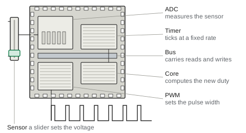
Microcontrollers: Microcontroller control loop: on each tick of a fixed timer the core reads the sensor through the ADC, computes a correction and writes a new duty to the PWM block over the bus; the PWM output pin then switches on and off with the new pulse width, so the output follows the sensorBuses and adapters: Serial bus: a host and three servos share one twisted pair with a terminating resistor at each end; the host sends a frame that starts with an address, every node receives it as it passes, only the servo with that address acts and then sends a reply frame back along the same pair
Power
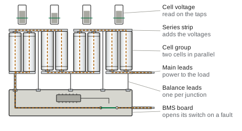
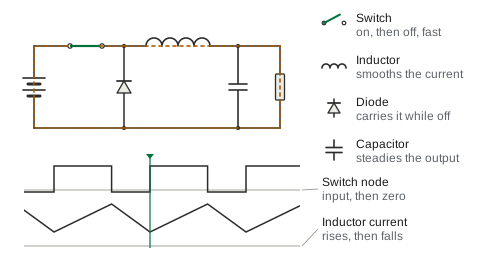
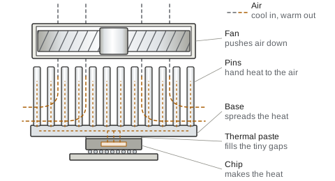
Battery packs: Battery pack: two cells in parallel make each group and four groups in series add their voltages; nickel strips join the cells, balance leads tap every junction for the BMS board, and current leaves by the main leads through the BMS switch; when one group sags out of range the BMS opens the switch, and closes it again when the group recoversPower converters: Buck converter: a switch connects the input in short pulses; while it is on, current flows from the input through the inductor to the load and the inductor current rises; while it is off, the inductor keeps the current flowing through the diode and the current falls; the capacitor holds a steady output below the input voltageCooling: Cooling: heat flows from the chip through a thin layer of thermal paste into the base of a pin-fin heat sink, spreads and rises into the pins; the fan above pushes cool air down between the pins, and the air leaves warm out of the sides, carrying the heat away
Structure and materials
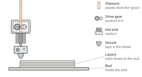
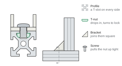
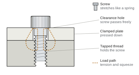
3D-print filaments: FDM 3D printing: a drive gear pushes the plastic filament into a hot end, where the heater block melts it; the nozzle moves along and lays a thin bead on the layer below, then rises one layer and lays the next, so the part grows layer by layer on the bedExtrusions: T-slot extrusion joint: a drop-in T-nut enters the slot edgewise and turns a quarter turn to lock under the slot lips; a corner bracket is set on the profiles, a screw passes through it into the nut, and tightening pulls the nut up against the lips, so the bracket clamps two profiles at a right angleFasteners: Bolted joint: a screw passes a clearance hole in the top plate and threads into a tapped hole in the bottom plate; turning it runs the head down onto the plate, and tightening further stretches the screw like a stiff spring and squeezes the plates together, the preload that holds the joint
End effectors
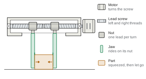
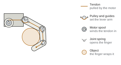
Grippers: Parallel gripper, front view with the housing cut open: a motor turns a lead screw that has a left-hand thread on one half and a right-hand thread on the other. A nut rides on each half and carries a jaw; the nuts cannot turn, so as the screw turns they move the same distance in opposite directions, one thread lead per turn. The jaws close on the part, stop and squeeze it, then open againHands: Tendon-driven finger, side view, cut open: a motor in the palm winds in a tendon that runs over a pulley at each joint and is tied to the tip. A spring in each joint holds the finger open; the tendon turns each free joint in proportion to its pulley size, so the base joint curls first. When a segment touches the object it stops and the joints beyond it keep curling, so the finger wraps the object base first, then middle, then tip. Letting the tendon out lets the springs open the finger